
Drainage route
Mark the beginning and end of the installation and check whether any other underground services run along the route.
A practical guide to trench preparation, establishing the correct gradient, selecting aggregate, using geotextile and correctly installing FOLKUL DRAIN drainage pipes with PP700 filtration wrap.
Before starting the work, determine the route of the installation, the water discharge point, installation depth, pipe diameter, gradient and the locations of the inspection chambers.
Mark the beginning and end of the installation and check whether any other underground services run along the route.
The system must have a clear and correctly positioned discharge point, such as a chamber, tank or downstream outlet.
Soil type, groundwater level, frost depth and surface loads affect the method used to construct the drainage system.
These instructions provide general guidance. The depth, diameter, layer thicknesses and gradient must be selected according to the design and the conditions of the specific project.
There is no single universal depth suitable for every installation. The soil type, foundations, groundwater level, loads and final discharge level must all be taken into account.
| Application type | Factors to consider | Recommendation |
|---|---|---|
| Perimeter drainage | Foundation and building waterproofing levels | Do not undermine the foundations; install according to the design |
| Land drainage | Ground gradient, water level and soil type | Select the depth according to the area requiring drainage |
| Agricultural drainage | Topsoil, soil conditions and drain spacing | Requires an assessment of water conditions and an individual design |
| Areas exposed to traffic loads | Loads and pavement structure | Provide suitable protection and proper compaction of the layers |
The pipe should be laid at a constant gradient towards the discharge point. In straightforward installations, a working gradient of approximately 0.5–1% is commonly used. The final value should, however, be determined by the design and the available difference in elevation.
| Gradient | Difference per metre | Difference over 10 metres | Information |
|---|---|---|---|
| 0.5% | 5 mm | 5 cm | Gentle working gradient |
| 0.8% | 8 mm | 8 cm | Clearly defined installation gradient |
| 1.0% | 10 mm | 10 cm | Easy to check on site |
Check the level along every section using a surveyor’s level, laser level or spirit level. A local depression in the pipe may cause water to stagnate and sediment to accumulate.
Pipe diameter selection should take into account the volume of incoming water, the drained area, rainfall intensity, surface type, installation length, gradient and ground conditions.
The formula is used to estimate the volume of water flowing from the drained area. It does not independently determine the capacity of a specific pipe.
The volume of water that must be collected and discharged by the system.
The area of land or structure from which water is collected.
The design rainfall value adopted for the project location.
Takes into account the type and permeability of the drained surface.
| Diameter | Typical application | Installation type | Selection guidance |
|---|---|---|---|
| Ø50–65 mm | Short sections and auxiliary drainage | Low water inflow | Requires individual assessment depending on length and gradient |
| Ø80 mm | Land drainage and shorter runs | Smaller drainage installations | Consider the ground conditions and expected water inflow |
| Ø100 mm | Perimeter and land drainage | Standard applications | A common choice for buildings and land drainage projects |
| Ø125 mm | Longer collector runs | Increased water inflow | Selection depends on installation length and number of branches |
| Ø160 mm | Collectors and larger systems | Large drainage installations | Requires hydraulic calculations and the correct gradient |
| Ø200 mm | Infrastructure and industrial projects | Extensive collector systems | Individual selection based on the project design |
Mark the pipe route, chamber locations and water discharge point.
Determine the starting level, final level and required gradient.
Allow sufficient space for the bedding, pipe, side fill and cover layer.
Remove sharp stones, roots, debris and any soft depressions.
If required by the design, line the bottom and sides of the trench with geotextile.
Lay and level a layer of clean, washed aggregate.
Unroll the pipe onto the bedding while maintaining the correct direction and constant gradient.
Install couplings, tees, elbows and inspection chambers.
Inspect the entire route before placing the surrounding aggregate.
Distribute the aggregate evenly along both sides and above the pipe.
Wrap the geotextile around the aggregate layer, maintaining the required overlap.
Take photographs and check the outlet, connections and inspection chambers.
The diagram shows the correct installation of a FOLKUL DRAIN drainage pipe with PP700 filtration wrap, surrounded by clean, washed aggregate and protected with separation geotextile.
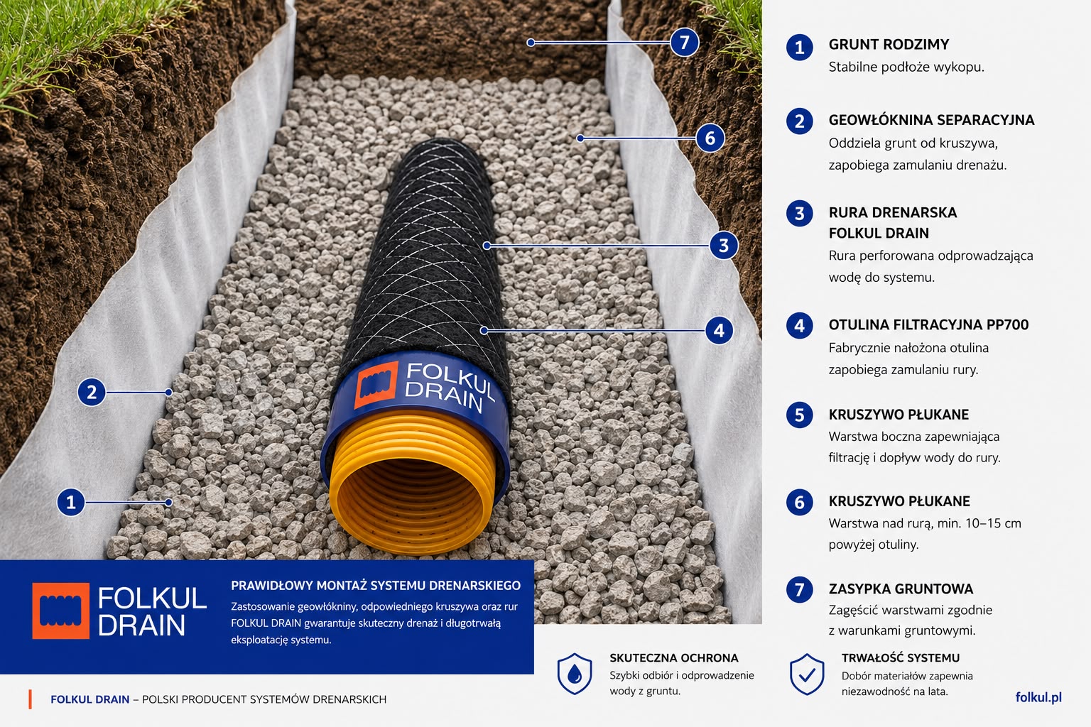
The geotextile forms a separation layer around the aggregate, while the PP700 filtration wrap remains directly on the pipe.
A levelled aggregate layer providing even support for the pipe.
Placed evenly along both sides of the drainage pipe.
Clean aggregate allows water to flow towards the filtration wrap.
The geotextile reduces mixing between the aggregate and surrounding soil.
The thickness of the bedding, side fill and cover above the pipe must be selected according to the pipe diameter, soil conditions, loads and project design.
Individual pipe sections should be connected using components matching the pipe diameter. Inspection chambers provide access for inspection, flushing and subsequent system maintenance.
Connect two straight pipe sections of the same diameter.
Allow branches to be created and the system diameter to be changed.
Provide inspection access and enable the drainage system to be cleaned.
No local depressions or sections running against the required gradient.
Couplings, tees, inspection chambers and the outlet are securely positioned.
The filtration wrap is not torn, displaced or otherwise damaged.
Water can leave the system freely and reach the designated discharge point.
The water has nowhere to discharge or the outlet is positioned too high.
Clay, silt and fine particles restrict water flow through the filtration zone.
Point support may cause the drainage pipe to settle or deform.
Backfilling without inspection makes later corrections significantly more difficult.
We will help you select the pipe diameter, filtration wrap, aggregate, fittings and inspection chambers to suit the conditions of your project.